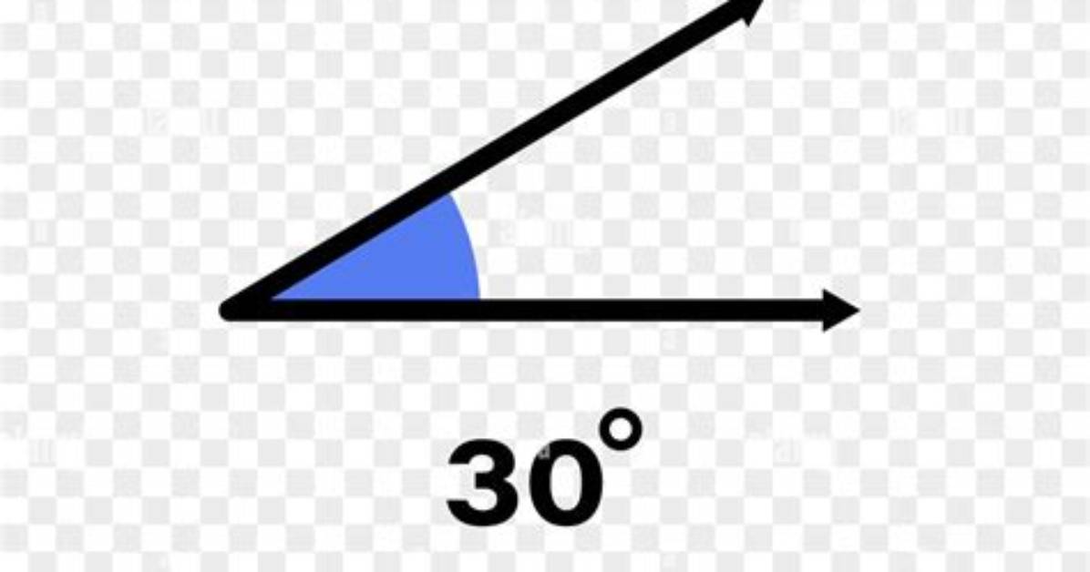
Adopting a 30-degree geometry across any mechanical discipline demands an honest assessment of physical trade-offs. The physics that makes thirty degrees so efficient also narrows operating margins.
In automotive engineering, a 30-degree valve seat reduces contact pressure between the valve face and the seat ring. When combustion pressures climb inside forced-induction or high-boost drag racing engines, a 45-degree angle remains the safer choice because it seals tighter under sheer brute force and sheds heat out of the valve head into the cylinder head cooling jackets more rapidly. A 30-degree seat must often run slightly wider contact margins, typically 0.060 to 0.080 inches on intake seats, to prevent premature valve face recession and valve head stretching.
In field blades, grinding down to a 30-degree inclusive profile exposes budget steels to micro-fractures. If a budget stainless steel like 420HC is ground to 15 degrees per side and used to chop frozen pine, the edge will inevitably ripple or chip. The geometry demands corresponding material strength: high fracture toughness, fine grain sizes, and hardness ratings above 60 HRC.
The baseline rules for application are straightforward:
- Opt for 30-degree geometry when prioritizing steady-state efficiency, high-velocity intake flow below 0.400-inch lift, low-friction cutting through ductile media, and aerodynamic glide paths that require predictable ground roll.
- Stick to traditional 45-degree configurations on exhaust valves subjected to extreme thermal loads, heavy-duty utility blades designed for pry-bar abuse, or high-boost forced induction engines where raw sealing pressure outranks natural aspiration airflow.

